8 ROBOT Construction Rules (R)
The rules listed below explicitly address legal parts and materials and how those parts and materials may be used on a REBUILT
There are many reasons for the structure of the rules, including safety, reliability, parity, creation of a reasonable design challenge, adherence to professional standards, impact on the competition, and compatibility with the Kit of Parts (
Another intent of these rules is to have all energy sources and active actuation systems on the
Many rules in this section reference Commercial-Off-The-Shelf (
Example 1: A team orders 2
Example 2: A team obtains openly available blueprints of a drive module commonly available from Wheels-R-Us Inc. and has local machine shop “We-Make-It, Inc.” manufacture a copy of the part for them. The produced part is not a
Example 3: A team obtains openly available design drawings from a professional publication during the pre-season and uses them to fabricate a gearbox for their
Example 4: A
Example 5: A team has a
Example 6: A team has a
A
- A. has a Federal Tax Identification number. In cases where the is outside of the United States, they must possess an equivalent form of registration or license with the government of their home nation that establishes and validates their status as a legitimate business licensed to operate within that country.VENDOR
- B. is not a “wholly owned subsidiary” of a FIRST Robotics Competition team or collection of teams. While there may be some individuals affiliated with both a team and the , the business and activities of the team andVENDORmust be completely separable.VENDOR
- C. should maintain sufficient stock or production capability so they are able to ship any general (i.e., non-FIRST unique) product within 5 business days of receiving a valid purchase request. It is recognized that certain unusual circumstances (such as such as a global supply chain disruption and/or 1,000 FIRST teams all ordering the same part at once from the same ) may cause atypical delays in shipping due to backorders for even the largestVENDOR. Such delays due to higher-than-normal order rates are excused. This criterion may not apply to custom-built items from a source that is both aVENDORSand a fabricator.VENDOR
For example, a
D. makes their products available to all FIRST Robotics Competition teams. A
The intent of this definition is to be as inclusive as possible to permit access to all legitimate sources, while preventing ad hoc organizations from providing special-purpose products to a limited subset of teams in an attempt to circumvent the cost accounting rules.
FIRST desires to permit teams to have the broadest choice of legitimate sources possible, and to obtain
Ideally, chosen
A FABRICATED ITEM is any
Note that it is possible for an item (typically raw materials) to be neither
Teams may be asked to provide documentation proving the legality of non-REBUILT
Some of these rules make use of English unit requirements for parts. If your team has a question about a metric-equivalent part’s legality, please e-mail your question to the FIRST Robotics Competition Kit of Parts team at frcparts@firstinspires.org for an official ruling. To seek approval for alternate devices for inclusion in future FIRST Robotics Competition seasons, please contact the Kit of Parts team at frcparts@firstinspires.org with item specifications.
Teams should acknowledge the support provided by the corporate sponsors and mentors with an appropriate display of their school and sponsors names and/or logos (or the name of the supporting youth organization, if appropriate).
FIRST Robotics Competition can be a full-contact competition and may include rigorous game play. While the rules aim to limit severe damage to
8.1 General ROBOT Design
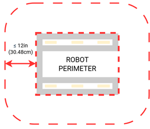
R101 *ROBOT PERIMETER must be fixed.
The
To determine the
Example: A
Figure 8‑1
R102 *STARTING CONFIGURATION – no overhang.
In the STARTING CONFIGURATION (the physical configuration in which a
If a
The allowance for minor protrusions in this rule is intended to allow protrusions that are both minor in extension from the
If a
R103 *ROBOT weight limit.
The
A.
B.
C. tags used for location detection systems if provided by the event.
R104 STARTING CONFIGURATION – max size.
A
Be sure to consider the size of the
Note that rules contained in section 8.4
R105 ROBOT horizontal extension limit.
Teams should expect to have to demonstrate a
R106 Horizontal extension – one direction at a time.
A.
B. Minor protrusions excluded from the
C.
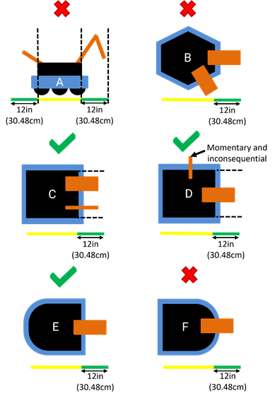
Examples of
Examples of compliance and non-compliance of this rule are shown in Figure 8‑3.
Yellow bars represent the limits of the
Green bars represent a measured extension from the
- A violates this rule for extending in more than one directionROBOT
- B violates this rule for extending in more than one directionROBOT
- C does not violate this ruleROBOT
- D does not violate this rule as the additional extension isROBOTand inconsequentialmomentary
- E does not violate this ruleROBOT
- F violates this rule for extending in more than one direction by extending over a round segment ofROBOTPERIMETER.ROBOT
Figure 8‑3 Examples of compliance and non-compliance of this rule

R107 ROBOT vertical extension limit.
This measurement is intended to be made as if the
8.2 ROBOT Safety & Damage Prevention
R201 *No digging into carpet.
Traction devices must not have surface features that could damage the
R202 *No exposed sharp edges.
Protrusions from the
Note that the use of acrylic or other materials which may break into jagged pieces is not explicitly prohibited, but any such breakage must be corrected immediately to comply with this rule.
R203 *General safety.
Examples of items that will violate this rule include (but are not limited to):
A. shields, curtains, or any other devices or materials designed or used to obstruct or limit the vision of any DRIVE TEAM members and/or interfere with their ability to safely
B. speakers, sirens, air horns, or other audio devices that generate sound at a
C. any devices or decorations specifically intended to jam or interfere with the remote sensing capabilities of another
D. lasers other than those listed as IEC/EN 60825-1 ”Class 1” or IEC/EN 62471 “Exempt,”
E. flammable gasses,
F. any device intended to produce flames or pyrotechnics,
G. hydraulic fluids or hydraulic items,
H. switches or contacts containing liquid mercury,
I. circuitry used to create voltages in excess of 24 Volts,
J. any ballast not secured sufficiently, including loose ballast e.g. sand, ball bearings, etc., such that it may become loose during a
K. hazardous materials (e.g. lead, whether encapsulated or not) used on the
L. high intensity light sources used on the
M. Bright lights which flash more than approximately 5 times per second, per E108.
R204 *Leave SCORING ELEMENTS at the FIELD.
Teams are encouraged to consider G501 when developing their
R205 *Don’t contaminate the FIELD.
Liquids, gels, greases and fine particles must not contaminate the
R206 *Don’t damage SCORING ELEMENTS.
SCORING ELEMENTS are expected to undergo a reasonable amount of wear and tear as they are handled by
8.3 Budget Constraints & Fabrication Schedule
R301 *Individual item cost limit.
No individual, non-KOP item or software shall have a Fair Market Value (FMV) that exceeds $600 USD. The total cost of
Teams should be ready to show
The Analog Devices IMU
The FMV of a
The FMV of
The FMV of FABRICATED parts is the value of the material and/or labor, except for labor provided by team members (including sponsor employees who are members of the team), members of other teams, and/or event provided machine shops. Material costs are accounted for as the cost of any purchasable quantity that can be used to make the individual part (i.e. the purchasable raw material is larger than the FABRICATED part).
Example 1: A team orders a custom bracket made by a company to the team's specification. The company’s material cost and normally charged labor rate apply.
Example 2: A team receives a donated sensor. The company would normally sell this item for $450 USD, which is therefore its FMV.
Example 3: A team purchases titanium tube stock for $400 USD and has it machined by a local machine shop. The machine shop is not considered a team sponsor but donates 2 hours of expended labor anyway. The team must include the estimated normal cost of the labor as if it were paid to the machine shop and add it to the $400 USD.
Example 4: A team purchases titanium tube stock for $400 USD and has it machined by a local machine shop that is a recognized sponsor of the team. If the machinists are considered members of the team, their labor costs do not apply. The total applicable cost for the part would be $400 USD.
It is in the best interests of the teams and FIRST to form relationships with as many organizations as possible. Recognizing supporting companies as sponsors of, and members in, the team is encouraged, even if the involvement of the sponsor is solely through the donation of fabrication labor.
Example 5: A team purchases titanium tube stock for $400 USD and has it machined by another team. The total applicable cost for the part would be $400 USD.
Example 6: A team purchases a widget at a garage sale or online auction for $300, but it’s available for sale from a
If a
If the modules are designed to assemble into a single configuration, and the assembly is functional in only that configuration, then the total cost of the complete assembly including all modules must fit within the price constraints defined in this rule.
In summary, if a
Example 7:
Example 8:
Example 9:
R302 *MAJOR MECHANISM, from this year only.
MAJOR
Neither this rule nor the language in this blue box define specific thresholds for how much of a MAJOR
Attempts to exploit loopholes in the definition of MAJOR
A. Pre-assembling significant portions of a MAJOR
B. Removing a small
R303 *Create new designs and software, unless they’re public.
Example 1: A team realizes that the transmission designed and built in the fall perfectly fits their need for a transmission to drive the
Example 2: A team developed an omni-directional drive system for the 2019 competition. In July 2019 they refined and improved the
Example 3: The same team decides to use LabVIEW as their software environment for REBUILT. Following Kickoff, they use the previously developed C++ code as a reference for the algorithms and calculations required to implement their omni-directional
Example 4: A different team develops a similar solution during the fall and plans to use the developed software on their competition
Example 5: A team develops a transmission prior to Kickoff. After completing the project, they publish the CAD files on a generally accessible public forum and make them available to all teams. Because they have made the design publicly available before Kickoff, they can use the design to create an identical transmission, fabricated after Kickoff, for use on their REBUILT
8.4 BUMPER Rules
A
A
All dimensions specified in this section are nominal and will be measured during inspection with a tolerance of 0.25in (0.63cm) unless otherwise specified. This means that maximums specified have a tolerance of +0.25in (0.63cm) and minimums specified have a tolerance of –0.25in (0.63cm). Teams are encouraged to design to the nominal dimension and reserve the tolerance for unexpected deviation such as manufacturing error or tolerance stack-up.
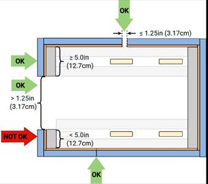
R401 *BUMPERS almost all around.
An arc is considered to have infinite corners and therefore may not have a gap larger than 1.25in (3.17cm).

R402 *BUMPER construction.
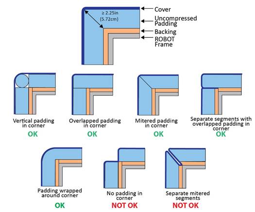
A. Padding – A minimum of 2.25in (5.72cm) depth of foam padding, at least 4.5in (11.43cm) tall consisting of solid blocks, sheets, or stacked rods of one or more of the following materials:
i. Solid pool noodles or backer rod
ii. Solid polyethylene closed cell foam (including crosslinked) with density between 1.5 and 3.0lb/ft3 (24.03 to 48.05kg/m3)
iii. Solid EVA closed cell foam with density between 2.0 and 6.0lb/ft3 (32.04 to 96.11kg/m3)
iv. Foam floor tiles
Multiple types, shapes, and/or layers of foam may be used within a single
Teams should be prepared to provide information about the padding material used in their
B. Backing – A backer at least 4.5in (11.43cm) tall which supports the padding (i.e. padding is not cantilevered other than in corners) and facilitates installation and removal of the
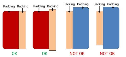
C. Cover – Cloth (as noted in R411) which covers all outward, upward and downward facing surfaces of padding such that no padding is exposed to interaction with the
D. Fastening System –
The
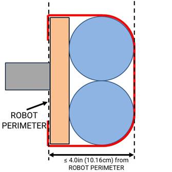
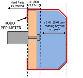
R403 *BUMPER extension limit.
R404 *BUMPERS must be soft.
Hard parts of
Hard parts include any items which are likely to cause damage to the cloth or padding of other
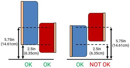
R405 *BUMPERS interact with BUMPERS.
While navigating the
This measurement is intended to be made in a
R406 *Fill BUMPER corners.
Corner joints between
Separate
R407 *BUMPERS shouldn’t be wedges.
Examples of
A.
B.
C.
R408 *Weight limit with BUMPERS.
The total weight of the
R409 *BUMPERS should be passive.
Compression and flex of
R410 *BUMPERS must come off.
As a guideline,
R411 *BUMPERS indicate your ALLIANCE.
Each
A. those required per R412,
B. hook-and-loop tape, snap fasteners, or functional equivalents backed by the hard parts of the
C. solid white FIRST logos between 4.75in (12.06cm) and 5.25in (13.33cm) wide (i.e. comparable to those available in the REBUILT Virtual Kit), and
D. narrow areas of underlying cloth exposed at seams, corners, or folds.
R412 *Team number on BUMPERS.
Team numbers must be displayed and positioned on the
A. consist of only white Arabic numerals at least 3.75in (9.53cm) high, at least 0.5in (1.27cm) in stroke width,
The 0.5in (1.27cm) stroke width requirement applies to the majority of the stroke. Font elements less than 0.5in (1.27cm) such as serifs, rounded edges, small hairlines or gaps, etc. are permitted as long as the majority of the stroke meets the sizing requirement and the numbers are unambiguous.
B. must not wrap around sharp corners (less than 135.0°) of the
C. must not split individual digits such that the team number is ambiguous, and
As a guideline, spacing between digits or groups of digits which exceeds ~4.0in (10.16cm) may be ambiguous.
D. may not substitute logos or icons for numerals.
There is no prohibition against splitting team numbers onto different sections of
This marking is intended to display the team number only, not to intentionally change the surface characteristics of the
8.5 Motors & Actuators
R501 *Allowable motors.
The only motors and actuators permitted include the following (in any quantity):
| Motor Name | Part Numbers Available | Part Numbers Available |
|---|---|---|
| AndyMark 9015 | am-0912 | AndyMark 9015 |
| AndyMark NeveRest | am-3104 | |
| AndyMark PG | am-2161 (alt. PN am-2765) | am-2194 (alt. PN am-2766) |
| AndyMark RedLine Motor | am-3775 | am-3775a |
| AndyMark Snow Blower Motor | am-2235 | am-2235a |
| Banebots | am-3830 M7-RS775-18 RS775WC-8514 | M5 – RS550-12 RS550VC-7527 RS550 |
| CIM | FR801-001 M4-R0062-12 AM802-001A 217-2000 PM25R-44F-1005 | PM25R-45F-1004 PM25R-45F-1003 PMR25R-45F-1003 PMR25R-44F-1005 am-0255 |
| CTR Electronics Minion | 24-777378 | WCP-1691 |
| CTR Electronics/VEX Robotics Falcon 500 | 217-6515 am-6515 | 19-708850 am-6515_Short |
| Current/former KOP | Denso AE235100-0160 Denso 5-163800-RC1 Denso 262100-3030 | Denso 262100-3040 Bosch 6 004 RA3 194-06 Johnson Electric JE-PLG-149 Johnson Electric JE-PLG-410 |
| Playing with Fusion Venom | BDC-10001 | |
| REV Robotics HD Hex | REV-41-1291 | |
| REV Robotics NEO Brushless | REV-21-1650 (v1.0 or v1.1) REV-21-1653 | am-4258 am-4258a |
| REV Robotics NEO 550 | REV-21-1651 | am-4259 |
| REV Robotics NEO Vortex | REV-21-1652 | am-5275 |
| Thrifty Bot Pulsar 775 | TTB-0350 | |
| VEX BAG | 217-3351 | |
| VEX Mini-CIM | 217-3371 | |
| West Coast Products Kraken x44 | WCP-0941 | |
| West Coast Products Kraken x60 | WCP-0940 | am-5274 |
| West Coast Products RS775 Pro | 217-4347 | |
| Fans, no greater than 120mm (nominal) size and rated electrical input power no greater than 10 watts (W) continuous | Fans, no greater than 120mm (nominal) size and rated electrical input power no greater than 10 watts (W) continuous | Fans, no greater than 120mm (nominal) size and rated electrical input power no greater than 10 watts (W) continuous |
| Hard drive motors part of a legal COTS | Hard drive motors part of a legal COTS | Hard drive motors part of a legal COTS |
| Factory installed vibration and autofocus motors resident in COTS | Factory installed vibration and autofocus motors resident in COTS | Factory installed vibration and autofocus motors resident in COTS |
| PWM COTS COTS | PWM COTS COTS | PWM COTS COTS |
| Motors integral to a COTS | Motors integral to a COTS | Motors integral to a COTS |
| 1 compressor compliant with R806 and used to compress air for the ROBOT | 1 compressor compliant with R806 and used to compress air for the ROBOT | 1 compressor compliant with R806 and used to compress air for the ROBOT |
COTS | COTS | COTS |
For servos, note that the roboRIO is limited to a max current output of 2.2A on the 6V rail (12.4W of electrical input power). Teams should make sure that their total servo power usage remains below this limit at all times.
Servo mechanical output power is approximated by the following formula (using 6V data reported by manufacturer): Mechanical Output Power (in W) = 0.25 x (Stall Torque in N-m) x (No Load Speed in rad/s). This calculator from the FIRST Tech Challenge documentation can be used to help calculate output power from inputs of various units.
Given the extensive amount of motors allowed on the
AndyMark PG Gearmotors are sold with labeling based on the entire assembly. Assemblies labeled am-3651 through am-3656 contain legal motors specified in Table 8‑1. These motors may be used with or without the provided gearbox.
R502 *Only 4 propulsion motors.
A
Examples that are not considered propulsion motors include:
A. motors that primarily alter the alignment of a wheel in contact with the
B. motors that run
C. motors that change the speed of the drive wheels using a shifting
D. motors that enable the
R503 *Don’t modify motors (mostly).
The integral mechanical and electrical system of any motor must not be modified. Motors, servos, and electric solenoids used on the
A. The mounting brackets and/or output shaft/interface may be modified to facilitate the physical connection of the motor to the
B. The electrical leads may be trimmed to length as necessary and connectors or splices to additional wiring may be added.
C. The locking
D. The connector housings on
E. Servos may be modified as specified by the manufacturer (e.g. re-programming or modification for
F. Minimal labeling may be applied to indicate device purpose, connectivity, functional performance, etc.
G. Any number of #10-32 plug screws may be removed from the Falcon 500 and the Kraken X60.
H. Insulation may be applied to electrical terminals.
I. Repairs, provided the original performance and specifications are unchanged.
J. Maintenance recommended by the manufacturer.
The intent of this rule is to allow teams to modify mounting tabs and the like, not to gain a weight reduction by potentially compromising the structural integrity of any motor.
R504 *Power (most) actuators off of approved devices.
With the exception of servos, fans, or motors integral to sensors of
A. motor controllers:
a. Koors40 Motor Controller (P/N am-5600),
b. Spark Flex Motor Controller (P/N REV-11-2159, am-5276)
c. Spark Motor Controller (P/N REV-11-1200, am-4260),
d. Spark MAX Motor Controller (P/N REV-11-2158, am-4261),
e. Talon FX Motor Controller (P/N 217-6515, 19-708850, am-6515, am-6515_Short, WCP-0940, WCP-0941) for controlling integral Falcon 500, Kraken X60, Kraken X44 only,
f. Talon FXS Motor Controller (P/N 24-708883, WCP-1692)
g. Talon Motor Controller (P/N CTRE_Talon, CTRE_Talon_SR, and am-2195),
h. Talon SRX Motor Controller (P/N 217-8080, am-2854, 14-838288),
i. Thrifty Nova (P/N TTB-0100),
j. Venom Motor with Controller (P/N BDC-10001) for controlling integral motor only,
k. Victor SP Motor Controller (P/N 217-9090, am-2855, 14-868380), and
l. Victor SPX Motor Controller (P/N 217-9191, 17-868388, am-3748).
B. relay modules:
a. Spike H-Bridge Relay (P/N 217-0220 and SPIKE-RELAY-H),
b. Automation Direct Relay (P/N AD-SSR6M12-DC-200D, AD-SSRM6M25-DC-200D, AD-SSR6M40-DC-200D), and
c. Power Distribution
C. pneumatics controllers:
a. Pneumatics
b. Pneumatic
D. servo controllers:
a. Servo
Note: The Automation Direct Relays are single directional. Per R504 they may not be wired together in an attempt to provide bi-directional
R505 *Don’t overload controllers.
Each power regulating device may
| Electrical Load | Motor Controller | Relay Module | Pneumatics Controller |
|---|---|---|---|
| AndyMark RedLine Motor Banebots CIM CTR Electronics Minion REV Robotics NEO Brushless REV Robotics NEO 550 REV Robotics NEO Vortex ThriftyBot Pulsar 775 VEX Mini-CIM WCP RS775 Pro | Yes | No | No |
| AndyMark 9015 VEXpro BAG | Yes (up to 2 per controller) | No | No |
| AndyMark PG KOP | Yes (up to 2 per controller) | Yes | No |
| Other Brushed Motor Linear Actuator | Yes (20A breaker max) | Yes (20A breaker max) | No |
| CTR Electronics/VEX Falcon 500 Playing With Fusion Venom WCP Kraken X44 WCP Kraken X60 | Yes (integrated controller only) | No | No |
| Compressor | No | Yes | Yes |
| Pneumatic Solenoid Valves | No | Yes (multiple) | Yes (1 per channel) |
| Electric Solenoids | Yes (multiple) | Yes (multiple) | Yes (1 per channel) |
| CUSTOM CIRCUITS | Yes (multiple) | Yes (multiple) | Yes (multiple) |
R506 *Control servos safely.
Servos must be connected to, and only to, 1 of the following:
A. PWM ports on the roboRIO,
B. PWM ports on a WCP Spartan Sensor Board (P/N WCP-0045),
C. REV Robotics Servo Power Module (P/N REV-11-1144), or
D. REV Robotics Servo
8.6 Power Distribution
In order to maintain safety, the rules in this section apply at all times while at the event, not just while the
R601 *Battery limit – everyone has the same power.
The only legal source of electrical energy for the
A. Nominal voltage: 12V
B. Nominal capacity at 20-hour discharge rate: minimum 17Ah, maximum 18.2Ah
C. Shape: Rectangular
D. Nominal Dimensions: 7.1in x 3.0in x 6.6in, +/- 0.1in for each dimension (18.03cm x 7.62cm x 16.76cm, +/-0.25cm for each dimension)
E. Nominal weight: 11.0lb to 14.5lb (4.99kg to 6.57kg)
F. Terminals: Nut and bolt style
G. Battery vents must not be obstructed during charging.
"Nut and bolt style" refers to any style battery terminal where the connector is secured to the battery using a threaded fastener.
Examples of batteries which meet these criteria include:
A. Enersys (P/N NP18-12, NP18-12B, NP18-12BFR),
B. MK Battery (P/N ES17-12),
C. Battery Mart (P/N SLA-12V18),
D. Sigma (P/N SP12-18),
E. Universal Battery (P/N UB12180),
F. Power Patrol (P/N SLA1116),
G. Werker Battery (P/N WKA12-18NB),
H. Power Sonic (P/N PS-12180NB),
I. Yuasa (P/N NP18-12B),
J. Panasonic (P/N LC-RD-1217),
K. Interstate Batteries (P/N BSL1116), and
L. Duracell Ultra Battery (P/N DURA12-18NB).
Teams should be aware that they may be asked to provide documentation of the specifications of any battery not listed above.
Batteries should be charged in accordance with manufacturer’s specification. (Please see the FIRST Safety Manual for additional information.)
While teams should generally attempt to leave the battery vent (the inset rectangle on the top face of the battery) as unobstructed as possible during charging, as long as the short edges of the rectangle are not sealed or directly covered the vent will be considered not obstructed.
R602 *Other batteries for cameras or computers only.
A. securely fastened to the
B. connected only using unmodified
C. charged according to manufacturer recommendations.
A
R603 *Charge batteries with safe connectors.
Any battery charger used to charge a
R604 *Charge batteries at a safe rate.
Any battery charger used to charge a
R605 *Batteries are not ballast.
No batteries other than those allowed per R601 and R602 are allowed on the
For example, teams may not use additional batteries as extra weight on their
R606 *Secure the battery.
The
R607 *Insulate battery connections.
Each electrical terminal on the
R608 *Limit non-battery energy.
Non-electrical sources of energy used by the
A. compressed air stored in the pneumatic system that has been charged in compliance with R806 and R807,
B. a change in the altitude of the
C. storage achieved by deformation of
D. closed-loop
E. air-filled (pneumatic) wheels.
R609 *Connect main power safely.
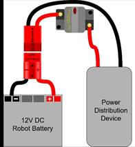
The following devices shall be connected with 6 AWG (7 SWG or 16 mm2) copper wire or larger as shown in Figure 8‑11:
A. 1
B. a single pair of Anderson Power Products (or APP) 2-pole SB type connectors
C. a single main 120-Amp (120A) surface mount circuit breaker (Cooper Bussman P/N CB185-120, CB185F-120, CB285-120 CB285F-120, CB285120F or Optifuse P/N 153120, 253120)
D. a single main power distribution device (PD):
a. CTR Electronics Power Distribution Panel (
b. CTR Electronics Power Distribution Panel 2.0 (
c. REV Robotics Power Distribution
d. AndyMark Power Distribution (AMPD) P/N am-5754
No additional devices or modifications shall be permitted with the following exceptions:
E. Monitoring circuitry permitted by R625
F. SB-50 to SB-120 adapters, provided they have been presented for Inspection
G. Termination of wires with appropriate cable lugs

“SB type” refers to SB type only (e.g. SB-50, SB-120, etc.), not SBS or any other part type beginning with SB. All batteries supplied by FIRST (such as Spare Parts and international batteries) will have a red or pink SB50 connector installed which may not be removed.
The pink connectors included in the
While pure copper wire is recommended, copper-clad aluminum wire is considered copper wire
R610 *1 breaker/fuse per circuit.
All circuits, with the exceptions of those listed in R615 and R617, must connect to, and have power sourced solely by, a single protected connector pair of the PD. Circuits must not connect to the main power input of the PD.
R611 *The ROBOT frame is not a wire.
All wiring and electrical devices shall be electrically isolated from the
Compliance with this rule is checked by observing a >120Ω resistance between either the (+) or (-) post within the APP connector that is attached to the PD and any point on the
All legal motor controllers with metal cases are electrically isolated. They may be mounted directly to
Note that some cameras, decorative lights, and sensors (e.g. some encoders, some IR sensors, etc.) have grounded enclosures or are manufactured with conductive plastics. These devices must be electrically isolated from the
R612 *Must be able to turn ROBOT on and off safely.
The 120A circuit breaker must be quickly and safely accessible from the exterior of the
Examples considered not “quickly and safely accessible” include breakers covered by an access panel or door, or mounted on, underneath or immediately adjacent to moving
It is strongly recommended that the 120A circuit breaker location be clearly and obviously labeled so it can be easily found by
While the main breaker must be accessible, consider positioning or shielding it such that it’s protected from accidental actuation (e.g. it’s unlikely to be hit by a SCORING ELEMENT during game play).
R613 *Electrical system must be inspectable.
The PD, associated wiring, and all circuit breakers must be visible for inspection.
“Visible for inspection” does not require that the items be visible when the
R614 *No high voltage allowed.
Any active electrical item that is not an actuator (specified in R501) or core
R615 *Power roboRIO as specified.
The roboRIO power input must be connected directly to a non-switched pair of protected output terminals of a PD with a 10A fuse or circuit breaker installed. No other electrical load can be connected to the breaker or fuse supplying this circuit.
R616 *Power radio as specified – Part 1.
The wireless bridge (radio) power must be connected based on the radio type:
A. For VH-109 radios, radio power must be sourced from one or both of:
a. Injected into the “RIO” port of the radio using a passive injector or modified Ethernet cable connected directly to a PD, and/or
b. Wired directly to the 12V power input of the radio from a PD.
B. For OM5P radios (China events only), radio power must be sourced from only one of:
a. the 12V/2A output of a CTR Electronics Voltage Regulator Module (
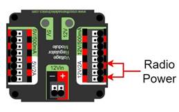
b. using an Ethernet cable between a REV Radio Power Module (
Note that this prohibits using any other active PoE injector device to power the radio but does not prohibit using any PASSIVE CONDUCTORS to inject the
Please reference How to Wire an FRC
R617 *Power radio as specified – Part 2.
The device supplying power to the wireless bridge per R616 must be connected directly to a non-switched pair of protected output terminals of a PD with a 10A fuse or circuit breaker installed with the exception of the
R618 *Use PD terminals as designed.
Only 1 wire shall be connected to each terminal on the PD.
If multi-point distribution of circuit power is needed (e.g. to provide power to multiple
R619 *Only use specified circuit breakers in a PD.
The only circuit breakers permitted for use in the PD are:
A. Snap Action VB3-A Series or AT2-A, terminal style F57, 40A rating or lower,
B. Snap Action MX5-A or MX5-L Series, 40A rating or lower,
C. REV Robotics ATO auto-resetting breakers 40A rating or lower,
D. CTR Electronics ATO auto-resetting breakers 40A rating or lower, and
E. Any ATM circuit breaker with value less than or equal to the fuses permitted per R620.
R620 *Only use specified fuses in PD.
The only fuses permitted for use in the PD are automotive blade fuses with the following values:
A. for the
B. for all PDs ATC/ATO style fuses with values 10A or lower, and
C. for the
Note that these fuses must be pressed very firmly to seat properly. Improper seating can cause a device to reboot upon impact.
R621 *Protect circuits with appropriate circuit breakers.
Each branch circuit must be protected by 1 and only 1 circuit breaker or fuse on the PD per Table 8‑3. No other electrical load can be connected to the breaker or fuse supplying this circuit with the exception of devices downstream of a permitted motor power adapter board placed between the PD and a motor controller (WCP-1380, WCP-1903, WCP-1904, RF-4003, RF-4004, RF-4005).
| Branch Circuit | Circuit Breaker/ Fuse Value | Quantity Allowed Per Breaker |
|---|---|---|
| Motor Controller | Up to 40A | 1 |
| CUSTOM CIRCUIT | Up to 40A | No limit |
| Automation Direct Relay 40A (6M40) | Up to 40A | 1 |
| Fans permitted per R501 and not already part of COTS | Up to 20A | No limit |
| Spike Relay Module | Up to 20A | 1 |
| Automation Direct Relay 25A (6M25) | Up to 20A | 1 |
PCM PH | Up to 20A | 1 |
| Servo Power Module/Servo Hub | Up to 20A | 1 |
| Additional VRM PCM PH | Up to 20A | 3 total |
| Automation Direct Relay 12A (6M12) | Up to 10A | 1 |
This rule does not prohibit the use of smaller value breakers in the PD or any fuses or breakers within CUSTOM CIRCUITS for additional protection.
Fans permitted per R501 may also be included within CUSTOM CIRCUITS.
R622 *Use appropriately sized wire.
All circuits shall be wired with appropriately sized insulated copper wire (SIGNAL
| Application | Minimum Wire Size |
|---|---|
| 31 – 40A breaker protected circuit | 12 AWG (13 SWG or 4 mm2) |
| 21 – 30A breaker protected circuit | 14 AWG (16 SWG or 2.5 mm2) |
| 6 – 20A breaker protected circuit | 18 AWG (19 SWG or 1 mm2) |
| 11-20A fuse protected circuit | 18 AWG (19 SWG or 1 mm2) |
| Between the PDP VRM RPM PCM PH | 18 AWG (19 SWG or 1 mm2) |
| Compressor outputs from the PCM PH | 18 AWG (19 SWG or 1 mm2) |
| Motor power adapter board protected circuit | 22 AWG (22 SWG or 0.5 mm2) |
| ≤5A breaker protected circuit | 22 AWG (22 SWG or 0.5 mm2) |
| ≤10A fuse protected circuit | 22 AWG (22 SWG or 0.5 mm2) |
VRM | 24 AWG (24 SWG or .25 mm2) Cat5e/6/7/8 cable, 2 pairs total (1 pair V+, 1 pair ground) |
| roboRIO PWM port outputs ≤1A fuse protected circuit | 26 AWG (27 SWG or 0.14 mm2) Cat5e/6/7/8 cable, single pair total |
| SIGNAL LEVEL continuous PCM PH VRM RPM | 28 AWG (29 SWG or .08 mm2) |
Wires that are recommended by the device manufacturer or originally attached to legal devices are considered part of the device and by default legal. Such wires are exempt from this rule, provided they are powered by the smallest value fuse or breaker which permits proper device operation.
In order to show compliance with these rules, teams should use wire with clearly labeled sizes if possible. If unlabeled wiring is used, teams should be prepared to demonstrate that the wire used meets the requirements of this rule (e.g. wire samples and evidence that they are the required size).
While pure copper wire is recommended, copper-clad aluminum wire is considered copper wire.
R623 *Use only appropriate connectors.
Branch circuits may include intermediate elements such as
Slip rings containing mercury are prohibited per R203.
R624 *Use specified wire colors (mostly).
All non-SIGNAL
A. red, yellow, white, brown, or black-with-stripe on the positive (e.g. +24VDC, +12VDC, +5VDC, etc.) connections,
B. black or blue for the common or negative side (-) of the connections
Exceptions to this rule include:
C. wires that are originally attached to legal devices and any extensions to these wires using the same color as the manufacturer,
D. Ethernet cable used in PoE cables.
R625 *Don’t modify critical power paths.
CUSTOM CIRCUITS shall not directly alter the power pathways between the
A noise filter may be wired across motor leads or PWM leads. Such filters will not be considered CUSTOM CIRCUITS and violate neither this rule nor R712.
Acceptable signal filters must be fully insulated and must be 1 of the following:
- 1 microfarad (1 µF) or less, non-polarized, capacitor may be applied across the power leads of any motor on your (as close to the actual motor leads as reasonably possible) orROBOT
- a resistor may be used as a shunt load for the PWM signal feeding a servo.control
R626 *VH-109 PoE passthrough.
The VH-109 PoE output may be used only under the following conditions:
A. The device being powered is a
B. The connection is made using standard Cat5e/6/7/8 cable.
C. The VH-109 is powered using the 12V input terminals with 18AWG wire or larger (it may additionally be powered using the PoE input if desired).
8.7 Control, Command & Signals System
R701 *Control the ROBOT with a roboRIO.
There are no rules that prohibit co-processors, provided commands originate from the roboRIO to enable and disable all power regulating devices. This includes motor controllers legally wired to the CAN bus.
R702 *Communicate with the ROBOT with the specified radio.
1 Vivid Hosting wireless bridge (P/N: VH-109, WCP-1538), that has been configured with the appropriate encryption key for your team number at each event, is the only permitted device for communicating to and from the
R703 *Use specific Ethernet port for roboRIO.
The roboRIO Ethernet port must be connected as specified:
A. For VH-109 v1.5 radios: to the port labeled “RIO” either directly, via a Cat5 Ethernet pigtail, or via a passive PoE injector cable or adapter.
B. For VH-109 v1.0 radios (either directly or via Cat5 Ethernet pigtail):
a. to the radio port labeled “RIO” via a passive PoE injector cable or adapter (whether or not it is used to power the radio), or an Ethernet cable with the appropriate wires removed on the roboRIO end. All wires or adapters used must be fully insulated, or
b. to the radio port labeled “AUX 1” or “AUX 2” with the corresponding DIP switch in the off (default) position.
C. For OM5P radios (China events only): to the wireless bridge port labeled “18-24v PoE” (either directly, via a network switch, via an
Note: Placing a switch between the roboRIO and radio may impede the ability for
If not using the “RIO” port of the VH-109 1.0, it is strongly recommended to cover the port to prevent accidental damage to devices such as laptops which may occur if attached to this port.
R704 *Only use allowed ports and bandwidth to communicate with the ROBOT.
Communication between the
A. 7.0Mbits/second for Vivid Hosting wireless bridge radios
B. 4.0Mbits/second for OpenMesh radios
| Port | Designation | Bi-directional? |
|---|---|---|
| UDP/TCP 1180-1190 | Camera data from the roboRIO to dashboard software when the camera is connected the roboRIO via USB | Yes |
| TCP 1735 | SmartDashboard | Yes |
| UDP 1130 | Dashboard-to-ROBOT control | Yes |
| UDP 1140 | ROBOT-to-Dashboard status data | Yes |
| HTTP 80 | Camera connected via switch on the ROBOT | Yes |
| HTTP 443 | Camera connected via switch on the ROBOT | Yes |
| UDP/TCP 554 | Real-Time Streaming Protocol for h.264 camera streaming | Yes |
| UDP/TCP 1250 | CTRE Diagnostics Server | Yes |
| UDP/TCP 5800-5810 | Team use | Yes |
Teams may use these ports as they wish if they do not employ them as outlined above (i.e. TCP 1180 can be used to pass data back and forth between the
Note that the 4.0Mbit limit will be strictly enforced by the wireless bridge.
The
While FIRST makes every effort to provide a wireless environment that allows teams access to a full 4.0Mbits/second data rate (with about 100.0Kbit used for
R705 *Configure devices for your team number.
The roboRIO,
R706 *Don’t bypass the ARENA network.
All signals must originate from the OPERATOR CONSOLE and be transmitted to the
R707 *Limited wireless allowed.
The only forms of wireless communication that may be used to communicate to, from, or within the
A. those required per R702 and R706,
B. tags used for location detection systems if provided by the event, and
C. RFID or NFC systems used exclusively within the
Devices that employ signals in the visual spectrum (e.g. cameras) and non-RF sensors that don’t receive human-originated commands (e.g. “beam break” sensors or IR sensors on the
R708 *Wireless bridge must be visible.
The wireless bridge must be mounted on the
Teams are encouraged to mount the wireless bridge away from noise generating devices such as motors,
R709 *ROBOTS must have a signal light.
Any
A. mounted on the
B. connected to the “
C. if using the 855PB-B12ME522, wired for solid light operation, by placing a jumper between the “La” and “Lb” terminals on the light per Figure 8‑13.
Please see How to Wire an FRC
R710 *Only specified modifications to control system devices permitted.
The
Please note that the
A. User programmable code in the roboRIO may be customized.
B. Motor controllers may be calibrated as described in owner's manuals.
C. Fans may be attached to motor controllers and may be powered from the power input terminals.
D. If powering the compressor, the fuse on a Spike H-Bridge Relay may be replaced with a VB3A-20A Snap-Action circuit breaker.
E. Wires, cables, and signal lines may be connected via the standard connection points provided on the devices.
F. Fasteners (including adhesives) may be used to attach the device to the OPERATOR CONSOLE or
G. Thermal interface material may be used to improve heat conduction.
H. Labeling may be applied to indicate device purpose, connectivity, functional performance, etc.
I. Jumpers may be changed from their default location.
J. Limit switch jumpers may be removed from a Jaguar motor controller and a custom limit switch circuit may be substituted.
K. Device firmware may be updated with manufacturer supplied firmware.
L. Integral wires on motor controllers may be cut, stripped, and/or connectorized.
M. Devices may be repaired, provided the performance and specifications of the device after the repair are identical to those before the repair.
N. The cover may be removed from the Talon SRX or Talon FX data port.
O. Electrical tape may be applied to the aluminum plate inside the wireless bridge.
P. The input terminal cover from the
Q. The roboRIO 2.0 SD card may be replaced with an SD card of any capacity.
S. replacing
T. tape may be applied for debris protection.
U. VH-109 v1.0 may be upgraded to VH-109 v1.5 using manufacturer materials and instructions.
Please note that while repairs are permitted, the allowance is independent of any manufacturer’s warranty. Teams make repairs at their own risk and should assume that any warranty or return options are forfeited. Be aware that diagnosing and repairing
For more information about modification O, please see this OM5P-AC Radio Modification article.
R711 *Don’t connect motor outputs to roboRIO.
Neither 12VDC power nor relay module or motor controller outputs shall be directly connected to the roboRIO, with the exception of the designated 12VDC input.
R712 *Control PWM controllers from the roboRIO.
Every relay module (per R504-B), servo, Servo Power Module, and PWM motor controller shall be connected to a corresponding port (relays to Relay ports, servos, and PWM controllers to PWM ports) on the roboRIO (either directly or through a WCP Spartan Sensor Board) or via a legal
R713 *Only approved MXP devices can control actuators.
If a motor is controlled via the
A. directly to any PWM
B. via a network of PASSIVE CONDUCTORS used to extend the PWM
C. via 1 approved ACTIVE DEVICE:
a. Kauai Labs navX
b. Kauai Labs navX2
c. RCAL
d. REV Robotics RIOduino
e. REV Robotics Digit Board
f. West Coast Products Spartan Sensor Board
g. Huskie Robotics HUSKIE 2.0 Board
A PASSIVE CONDUCTOR is any device or circuit whose capability is limited to the conduction and/or static regulation of the electrical energy applied to it (e.g. wire, splices, connectors, printed wiring board, etc.).
An ACTIVE DEVICE is any device capable of dynamically controlling and/or converting a source of electrical energy by the application of external electrical stimulus.
The “network of PASSIVE CONDUCTORS” only applies to the
R714 *Control CAN motor controllers from the roboRIO.
Each CAN motor controller must be controlled with enable/disable inputs sourced from the roboRIO and passed via either a PWM (wired per R713) or CAN bus (either directly or daisy-chained via another CAN bus device) signal, but both shall not be wired simultaneously on the same device.
As long as the CAN bus is wired legally so that the heartbeat from the roboRIO is maintained, all closed loop
“Wired directly” includes via any series of PASSIVE CONDUCTORS (i.e. star or
R715 *Control PCM, PH, and Servo Hub from roboRIO.
Each Pneumatic
R716 *Don’t alter the CAN bus.
No device that interferes with, alters, or blocks communications among the roboRIO and the
Only 1 wire should be inserted into each Weidmuller CAN connector terminal. For documentation on how to wire the CAN bus connections see How to Wire an FRC
R717 *USB to CAN adapter permitted.
Additional CAN bus connections may be added to the roboRIO using the CTR Electronics CANivoreTM (P/N 21-678682, WCP-1522) USB-to-CAN adapter.
Any additional CAN bus added in this manner satisfies the requirements of R714 (i.e. you may connect motor controllers to this additional bus).
8.8 Pneumatic System
In order to maintain safety, the rules in this section apply at all times while at the event, not just while the
R801 *Only use explicitly permitted pneumatic parts.
To satisfy multiple constraints associated with safety, consistency, inspection, and constructive innovation, no pneumatic parts other than those explicitly permitted in this section shall be used on the
R802 *No custom pneumatics and meet minimum pressure ratings.
All pneumatic items must be
A. rated by their manufacturers for pressure of at least 125.0psi (861.8kPa, 8.618Bar), or
B. installed downstream of the primary relieving regulator (see R809), and rated for pressure of at least 70.0psi (482.6kPa, 4.826Bar).
Any pressure specification such as “working,” “operating,” “maximum,” etc. may be used to satisfy the requirements of this rule.
It is recommended that all pneumatic items be rated by their manufacturers for a working pressure of at least 60.0psi (413.7kPa, 4.137Bar).
R803 *Don’t modify pneumatics.
All pneumatic
A. tubing may be cut,
B. wiring for pneumatic devices may be modified to interface with the
C. assembling and connecting pneumatic
D. removing the mounting
E. labeling applied to indicate device purpose, connectivity, functional performance, etc.
Do not, for example, paint, file, machine, or abrasively remove any part of a pneumatic
R804 *Only use specific pneumatic devices.
The only pneumatic system items permitted on
A. pneumatic pressure vent plug valves functionally equivalent to those provided in the
Examples of acceptable valves include Parker PV609-2 or MV709-2.
B. pressure relief valves functionally equivalent to those provided in the
Examples of acceptable valves include Norgren 16-004-011, 16-004-003 or McMaster-Carr 48435K714.
To be considered functionally equivalent the valve must be preset or adjustable to 125.0psi (861.8kPa, 8.618Bar) and capable of relieving at least 1.0scfm (471.9cm3/s).
C. solenoid valves with a maximum ⅛in (nominal, 0.31cm) NPT, BSPP, or BSPT port diameter or integrated quick connect ¼in (nominal, 0.64cm) outside diameter tubing connection,
D. additional pneumatic tubing, with a maximum ¼in (nominal, 0.64cm) outside diameter,
E. pressure transducers, pressure gauges, passive flow
F. check and quick exhaust valves, provided that the requirements of R813 are still met,
G. shutoff valves which relieve downstream pressure to atmosphere when closed (may also be known as 3-way or 3-way exhausting valves),
H. pressure regulators with the maximum outlet pressure adjusted to no more than 60.0psi (413.7kPa, 4.137Bar),
I. pneumatic cylinders, pneumatic linear actuators, and rotary actuators,
J. pneumatic storage tanks (with the exception of white Clippard tanks P/N AVT-PP-41),
K. 1 compressor that is compliant with R806,
L. debris or coalescing (water) filters, and
M. Venturi valves (note: the high-pressure side of a Venturi valve is considered a pneumatic device and must follow all pneumatic rules. The vacuum side of a Venturi valve is exempt from the pneumatic rules per “a” in the blue box below).
The following devices are not considered pneumatic devices and are not subject to pneumatic rules (though they must satisfy all other rules):
A. a device that creates a vacuum,
B. closed-loop
C. air-filled (pneumatic) wheels, and
D. pneumatic devices not used as part of a pneumatic system (i.e. used in a way that does not allow them to contain pressurized air)
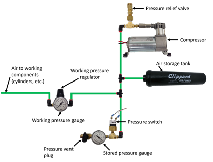
R805 *If using pneumatics, these parts are required.
If pneumatic
A. 1 FIRST Robotics Competition legal compressor (per R806),
B. a pressure relief valve (per R804-B) connected and calibrated (per R811),
C. a Nason pressure switch (P/N SM-2B-115R/443) and/or REV Robotics Analog Pressure Sensor (P/N REV-11-1107) connected and wired per R812,
D. at least 1 pressure vent plug plumbed (per R813),
E. stored pressure gauge and working pressure gauge (per R810), and
F. 1 primary working pressure regulator (per R808).

R806 *Compressed air from ROBOT compressor only.
Throughout an event, compressed air on the
A
Note: Viair C-series compressors, which have a max working pressure of 120.0psi, are rated for intermittent pressures greater than 125.0psi and therefore meet the requirements of this rule.
R807 *Air storage pressure limit.
Stored air pressure on the
R808 *Working air pressure limit.
Working air pressure (air pressure used to actuate devices) on the
Examples of acceptable valves include Norgren regulator P/N R07-100-RNEA and Monnier P/N 101-3002-1.
R809 *Limited devices at high pressure.
Only the compressor, relief valve, pressure switch, pressure vent plug, pressure gauge, storage tanks, tubing, pressure transducers, filters, and connecting fittings may be in the high-pressure pneumatic circuit upstream from the regulator.
It is recommended that all
R810 *Pressure gauges must be visible.
Pressure gauges must be placed in easily visible locations upstream and downstream of the regulator to display the stored and working pressures, respectively. Pressure gauges must show pressure in psi, kPa, or Bar.
R811 *Relief valve requirements.
The relief valve must be attached directly to the compressor or attached by legal hard fittings (e.g. brass, nylon, etc.) connected to the compressor output port.
Teams are required to check and/or adjust the relief valve to release air at 125.0psi (861.8kPa, 8.618Bar). The valve may or may not have been calibrated prior to being supplied to teams.
Instructions for adjusting the pressure relief valve can be found in the Pneumatic Manual.
R812 *Pressure switch requirements.
The pressure switch must be connected to the high-pressure side of the pneumatic circuit (i.e. prior to the pressure regulator) to sense the stored pressure of the circuit.
It must be either:
A. Nason P/N SM-2B-115R/443 (wired as described) and/or
The 2 wires from the pressure switch must be connected directly to the pressure switch input of the
B. REV Robotics P/N REV-11-1107 (wired as described)
The analog output of the sensor must be connected directly to analog input 0 of the
The REV Robotics Analog Pressure Sensor may only be used with
R813 *Vent plug requirements.
Any pressure vent plug must be:
A. connected to the pneumatic circuit such that, when manually operated, it will vent to the atmosphere to relieve all stored pressure in a reasonable amount of time and
B. placed on the
R814 *Don’t connect solenoid outputs together.
The output air from multiple solenoid valves must not be combined.
Manifolds, shuttle valves, and other devices which do not combine output airflow, even though it may be plumbed into the same device, are not violations of this rule.
8.9 OPERATOR CONSOLE
R901 *Use the specified Driver Station Software.
The
Teams are permitted to use a portable computing device of their choice (laptop computer, tablet, etc.) to host the
R902 *The OPERATOR CONSOLE must have a visible display.
The OPERATOR CONSOLE, the set of
R903 *Connect FMS Ethernet directly to the OPERATOR CONSOLE.
Devices hosting the
Teams are strongly encouraged to use pigtails on the Ethernet port used to connect to the
R904 *OPERATOR CONSOLE physical requirements.
The OPERATOR CONSOLE must not
A. be longer than 60.0in (1.524m),
B. be deeper than 16.0in (40.64cm) (excluding any items that are held or worn by the
C. extend more than 78.0in (1.981m) above the floor, or
D. attach to the
There is a 54.0in (1.372m) long by 2.0in (nominal, 5.08cm) wide strip of hook-and-loop tape (“loop” side) along the center of the
Please note that while there is no hard weight limit, OPERATOR CONSOLES that weigh more than 30lb (13.61kg) will invite extra scrutiny as they are likely to present unsafe circumstances.
R905 *FIELD wireless only.
Other than the system provided by the
Examples of prohibited wireless systems include, but are not limited to, active wireless network cards and Bluetooth devices. For the case of the FIRST Robotics Competition, a motion sensing input device (e.g. Microsoft Kinect) is not considered wireless communication and is allowed.
R906 *No unsafe OPERATOR CONSOLES.
OPERATOR CONSOLES shall not be made using hazardous materials, be unsafe, cause an unsafe condition, or interfere with other DRIVE TEAMS or the operation of other
R907 *No AC inverters.
OPERATOR CONSOLES must not contain AC inverters.