5 ARENA
The
5.1 Dimensions and Accuracy
All official models for the REBUILT

The specification for the REBUILT
- The 3D CAD model is the official representation of the REBUILT and how it is constructed.FIELD
- Illustrations included in this section are for a general visual understanding of the REBUILT , and dimensions included in the manual are nominal and no tolerances are implied. Please refer to the official drawings for exact dimensions, tolerances, and construction details.ARENA
- The Dimension Drawings package has critical dimensions for eachFieldelement.FIELD
- The Manual includes instructions on how to build theFIELDalong with showing the ways construction type will influence theFIELDtolerances. It also includes many of the key dimensions which are listed in the OfficialfieldDrawings.FIELD
- The Acceptance Checklist (coming soon) includes the controlled dimensions (with relevant tolerances) which will be checked by event staff a few times throughout the event. TheFIELDis expected to change duringFIELDplay. Teams can ask theMATCHto re-check specific measurements if they believe something is out of spec prior to aFTAbeginning.MATCH
The official drawings, CAD models, and drawings for low-cost versions of important elements of the REBUILT
The
However,
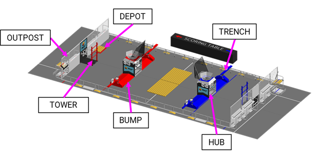
5.2 FIELD
Each
The
- 1 perOUTPOST,ALLIANCE
- 1 perHUB,ALLIANCE
- 1 perTOWER,ALLIANCE
- 2 ,DEPOTS
- 4 , andBUMPS
- 4 .TRENCHES
The surface of the
Carpet edges and seams are secured with 3MTM Premium Matte Cloth (Gaffers) Tape GT2, GT3 or comparable Gaffer’s Tape. Tears, rips, and damage to the carpet may be repaired with the same styles of tape and
Guardrails form the long edges of the

There are 2 versions of guardrails and
Table 5‑2 illustrate which areas have each kind of
| District | Field |
|---|---|
| FIRST Chesapeake | AndyMark |
| FIRST California | Welded |
| FIRST in Michigan | Welded |
| FIRST in Texas | AndyMark |
| FIRST Indiana Robotics | AndyMark |
| FIRST Israel | Welded |
| FIRST Mid-Atlantic | Welded |
| FIRST North Carolina | AndyMark |
| FIRST South Carolina | Welded |
| FIRST Wisconsin | AndyMark |
| NE FIRST | AndyMark |
| Ontario | Welded |
| Pacific Northwest | Welded |
| Peachtree | Welded |
| Regional Location | Field |
|---|---|
| Australia | Welded |
| Brazil | AndyMark |
| Canada | Welded |
| China | AndyMark |
| Mexico | AndyMark |
| Türkiye | AndyMark |
| United States | Welded |
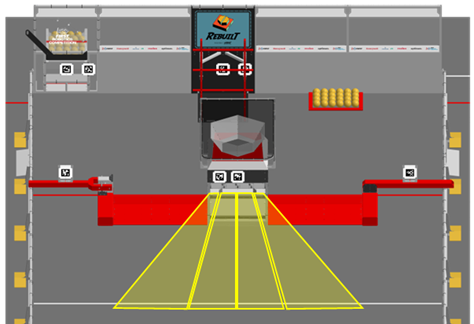
5.3 Areas, Zones, & Markings
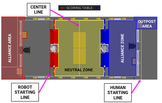
- AREA: an approximately 360in wide by 134in deep (~9.14m by 3.4m) infinitely tall volume formed by, and including theALLIANCEWALL,ALLIANCE,OUTPOSTWALL, the edge of the carpet, andTOWERcolored tape perpendicular to theALLIANCESTATIONS.DRIVER
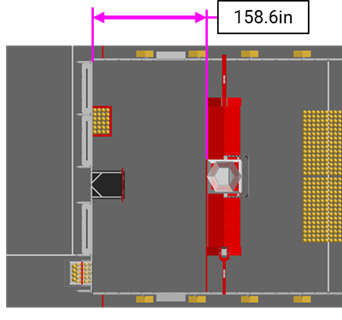
- ZONE: A 158.6in deep by 317.7in long (~4.03m by 8.07m), infinitely tall volume formed by anALLIANCEWALL,ALLIANCEWALL, and guardrails. It surrounds anTOWERALLIANCEand aTOWER. It is bounded by and includes theDEPOTSTARTING LINE.ROBOT
- CENTER LINE: a white line that spans the width of the that bisects the NEUTRAL ZONE in half.FIELD
- NEUTRAL ZONE: A 283in deep by 317.7in long (7.19m by 8.07m), infinitely tall volume formed by the ,BUMPS,TRENCHES, and guardrails. It surrounds and includes the CENTER LINE.HUBS
- HUMAN STARTING LINE: a white line spanning the AREA up to theALLIANCEAREA that is parallel to and located 24.0in (61.0cm) from the bottom square tube of theOUTPOSTWALL to the near edge of the tape.ALLIANCE
- AREA: a 71.0in wide by 134in deep (1.8m by 3.4m) infinitely tall volume bounded by theOUTPOST, edge of carpet, andOUTPOSTand white colored tape.ALLIANCE
- STARTING LINE: anROBOTcolored line that spans the width of theALLIANCEat the edge of anFIELDZONE in front of twoALLIANCEand anBUMPSALLIANCE.HUB
5.4 HUB

A
The top of each
The top angles of the
| Color | Pre-MATCH | MATCH | Post-Match |
|---|---|---|---|
ALLIANCE | N/A | HUB | N/A |
ALLIANCE | N/A | HUB | N/A |
ALLIANCE | N/A | During the TRANSITION SHIFT ALLIANCE HUB ALLIANCE SHIFT HUB | N/A |
| Purple | N/A | N/A | FIELD FIELD |
| Green | N/A | N/A | FIELD |
| Off | MATCH | HUB | N/A |
5.5 BUMP
5.6 TRENCH
5.7 DEPOT
A
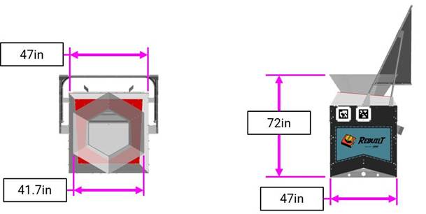
5.8 TOWER

A
The
The
The
The
Each
5.9 ALLIANCE WALL
The
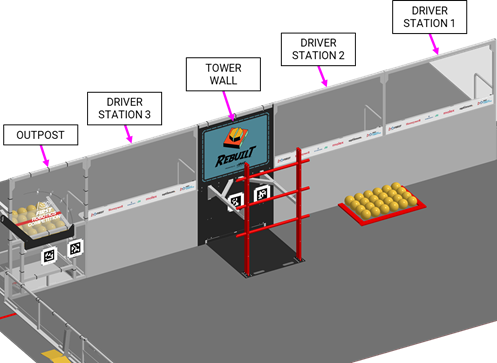
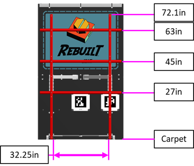
5.9.1 DRIVER STATIONS
A
An aluminum shelf is attached to each
There is a 6.0in (15.2cm) tall sponsor panel in each
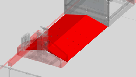
There may be a ramp available at events for DRIVE TEAMS with limited mobility. It is designed to allow an individual using a wheelchair to access the
This ramp is available at many Regional and District events. For questions, please connect with the local Program Delivery Partner.
Teams should also speak to the
Each
- 1 Ethernet cable: attaches to the Ethernet port of the OPERATOR CONSOLE and provides connectivity to the Management System (FIELD).FMS
- 1 120VAC NEMA 5-15R power outlet (i.e. standard US outlet): located on each STATION shelf and protected by its own 2-Amp circuit breaker. It can be used to power the OPERATOR CONSOLE. DRIVE TEAMS are responsible for monitoring their power consumption as a tripped breaker in the outlet does not constitute anDRIVERFAULT. For some events in regions that don’t use NEMA 5-15 shaped outlets, event organizers may install appropriate plug adapters to be used throughout the event.ARENA
- 1 Emergency Stop (E-Stop) button: located on the left side of the STATION shelf and is used to deactivate aDRIVERin an emergency.ROBOT
- 1 Autonomous Stop (A-Stop) button: located on the right side of the STATION shelf and is used to DISABLE aDRIVERduringROBOT.AUTO
- 1 team sign: located at the top of each STATION. TheDRIVERfacing side of the sign displays the team number in theFIELDcolor. TheALLIANCEAREA side of the sign displays the following information in red:ALLIANCE
- o Pre-MATCH: team number and connection stateROBOT
- o During Qualification :MATCHES
- Current and time remaining in that period,SHIFT
- A shows for when bothAUTO’sALLIANCEare activeHUBS
- T shows for the TRANSITION when bothSHIFT’sALLIANCEare activeHUBS
- shows when the RedR’SALLIANCEis activeHUB
- B shows when the Blue ’SALLIANCEis activeHUB
- E shows for END GAME when both ’sALLIANCEare activeHUBS
- Progress towards the Ranking Points. This shows total scored out of the ENERGIZEDFUELand once that threshold passes it shows out of the SUPERCHARGEDRPRP
- AUTOpoints, andTOWER
- remaining period time.MATCH

- o During the during PlayoffMATCH:MATCHES
- Which period is active and time remaining in that period,MATCH
- scores, andMATCH
- remaining period time.MATCH

- 1 timer (in STATION 2 only): displays the official time remaining in theDRIVERperiod on the FIELD-facing side (in white) and on the team facing side the following information in red:MATCH
- o remaining period time, andMATCH
- o scores.MATCH
- 1 team LED stack: indicates color,ALLIANCEstatus, E-Stop and A-Stop status, and is centered at the top of eachROBOTSTATION. The stack includes 2 identical ALLIANCE-coloredDRIVERstatus LEDs above a third amber A-stop/E-stop LED. LED states are as follows:ROBOT
- o status LEDsROBOT
- Solid: indicates that the is connected and enabled. This only happens during aROBOT.MATCH
- Blinking: indicates that either the is preset for theFMSand theMATCHis not connected yet, or it’s during aROBOTand the correspondingMATCHhas lost connectivity, or the E-stop was pressed.ROBOT
- Off: indicates that the is linked andROBOTprior to the start of theDISABLED, or theMATCHisROBOT. This light is also off, regardless ofBYPASSEDconnection status, after theROBOThas concluded.MATCH
- o A-Stop/E-stop LED
- Solid: the isROBOTdue to a press of the team E-stop button, theDISABLEDE-stop button, or by the scorekeeper via theFIELD.FMS
- Blinking: the isROBOTfor the remainder ofDISABLEDdue to a press of the team A-Stop button.AUTO
- Off: the is notROBOTby theDISABLED.FIELD
- hardware and wiring: mostly located below shelves in the 2FMSSTATIONS closer to the scoring table.DRIVER
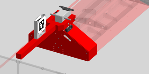
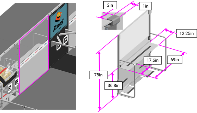
5.9.2 OUTPOST
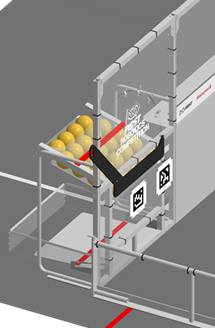
An
A 15.0° sloped tunnel, called the
At the base of the
The
There are 2 stools available at events for DRIVE TEAMS to use. Each stool is 23.0in (58.42cm) wide by 13.5in (34.29cm) deep, 6.25in (15.88cm) tall, and rated for 300lb (136.0kg).
It is specially intended to allow individuals who are shorter, better sightlines onto the
Only 2 stools are available, and priority will be given to those with the biggest need. Teams should speak to the
This stool is available at all events within the US & Canada and equivalents are available at international events. For questions, please connect with the local Program Delivery Partner.
5.10 SCORING ELEMENTS
SCORING ELEMENTS are items that teams use to score points. There is one type of SCORING ELEMENT used in REBUILT:
In REBUILT, a
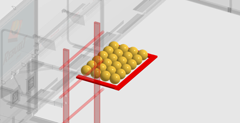
5.10.1 FUEL
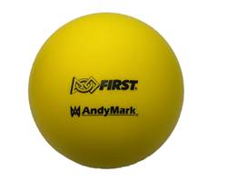
A
Most new
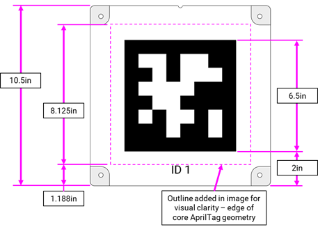
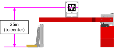
5.11 AprilTags
AprilTags are 8.125in (20.64cm) square targets located on the
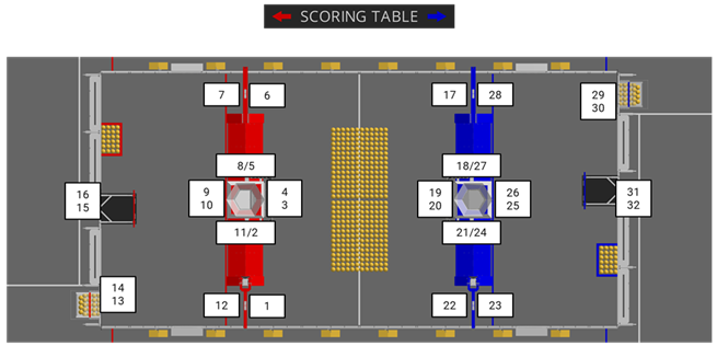
All markers are from the 36h11 tag family, IDs 1-32. All AprilTags are mounted to and centered on a 10.5in (26.67cm) square polycarbonate panel. Each marker has an identifying text label. If AprilTags experience wear and marking during
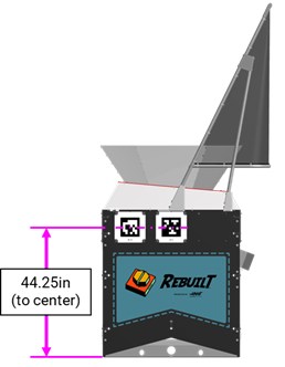
Two AprilTags (IDs 15, 16, 31, 32) are located on each
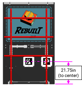
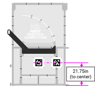
Two AprilTags (IDs 13, 14, 29, 30) are located on each
For further marker locating information please refer to the 2026
5.12 The FIELD Management System
The
When a DRIVE TEAM connects the Ethernet cable from their assigned
Note that
The
| Event | Timer Value(s) | Audio Cue |
|---|---|---|
MATCH | 0:20 (for AUTO | “Cavalry Charge” |
AUTO | 0:00 (for AUTO | “Buzzer” |
TELEOP | 2:20 | “3 Bells” |
ALLIANCE SHIFT | 2:10 1:45 1:20 0:55 | “POWER UP – Linear Popping” |
| END GAME begins | 0:30 | “Steam Whistle” |
MATCH | 0:00 | “Buzzer” |
MATCH | n/a | “Foghorn” |
5.13 FIELD STAFF
- Head – trains, directs, and supervisesREFEREE. They oversee all scoring processes and procedures in collaboration with the FIRST Technical Advisor (REFEREES). They interact withFTA, volunteers, and contracted/FIRST staff. The HeadSTUDENTSis positioned between theREFEREEand the scoring table and wears a yellow shirt. The HeadFIELDhas final authority for decisions regardingREFEREEscores, penalties, and YELLOW and RED CARD assignments. For additional details, please refer to the HeadMATCHrole description.REFEREE
- FIRST Technical Advisor () - ensures events run smoothly, safely, and in accordance with FIRST requirements. TheFTAcollaborates with FIRST staff, event staff, and other event volunteers in many different areas at events. TheFTAis the liaison between FIRST HQ and the event for all things related to theFTA,FIELD, and game, acts as a team advocate for all teams competing at the event and is a major point of escalation and conflict resolution for the event. For additional details, please refer to theROBOTSrole description.FTA
- Supervisor - directs activity on theFIELDto ensure efficient execution of theFIELD, pacing of the event, and smooth flow ofMATCHESplay.MATCHSupervisors are responsible for ensuring theFIELDis intact and leadFIELDReset teams, who are responsible for resetting theFIELDafter eachFIELDin preparation for the subsequentMATCH. For additional details, please refer to theMATCHSupervisor role description.FIELD